A practical guide for cracking AES-128 encrypted firmware updates
Posted by Mark Kirschenbaum on
[Revision 2, 10-14-2020]
A couple years ago, I began my journey to dump a secure device's firmware. I spent an ungodly amount of time attempting to find a vulnerability without avail. With my new found time not working skydiving events this season, I decided it was time to take the gloves off, learn a new skill, and Side Channel Attack the target.
Why?
My purpose here is to shed some light on the practical implementations of this attack, including where I went wrong, and the steps that ultimately allowed me to extract the bootloader's 128bit encryption key.
What started out as just my lab notes, has evolved in to a fairly complete guide. References are linked throughout this article that have been instrumental in educating me to perform the attack.
This attack is not easy. Your first one on real hardware will take weeks if not months of commitment. However, successfully accomplishing your first attack is beyond rewarding. I'm still learning, but feel this documentation is valuable for those on the same quest.
Sections
- Side Channel Attacks Overview
- Cryptography or how I fall asleep at night
- AES for Side Channel Attacks
- That S-Box tho'
- Key Schedule
- Inverse Shift Rows
- The Missing Link
- Hamming Weight
- Attacking the Victim
- Hardware Considerations
- Answers to Questions I Had When I Started
- What You'll Need to Perform Your First Real Attack
- Conclusion
Side Channel Attacks Overview
As an attacker, a Side Channel Attack (SCA) is trying everything but the "front door" to extract the secret out of a secure device. Attacks such as timing attacks, power glitching, electromagnetism fault injection, and even laser injection all fall into this category. Even speculative execution bugs such as Spectre and Meltdown are Side Channel Attacks. For those new to SCA, Crypto Fails has a good Introduction into Side Channel Attacks post.
In the end, I'm going to walk you through how sensing the power consumption of a target's secure microcontroller enable us to recover the update encryption keys.
With that said, if learning how to perform Side Channel Attacks on Microcontrollers interest you, I highly suggest you look in to getting a ChipWhisperer Lite or even a Nano. It's the easiest way to learn these techniques and I heavily rely on it's ecosystem to attack the target.
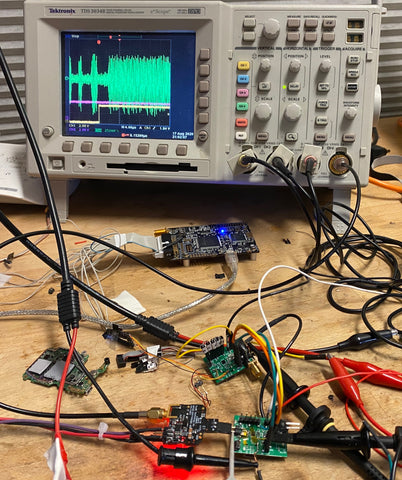
Figure: One of my original Side Channel Attack setups
Cryptography or How I Fall Asleep
Since validating cryptography is extremely math intensive, it always appears more cryptic than necessary to outsiders. In this article, I'll focus on the important concepts one needs to know about AES (Advanced Encryption Standard) to extract the encryption key via a Side Channel Attack.
As seen below it's super easy..... Don't LEAVE I'll make it easier
Figure: AES is easy credit: moserware.com

If your AES knowledge is lacking, as mine was when I first started, I really suggest watching this video to get up to speed AES Explained (Advanced Encryption Standard) by Computerphile. He does a very good job at bringing the encryption algorithm down to its fundamentals without too much "academic speak".
AES for Side Channel Attacks
From a side channel attack standpoint, we really don’t care too much about the finer details of each step but it makes it easier if we know generally what each step does.
Figure: AES decryption flow
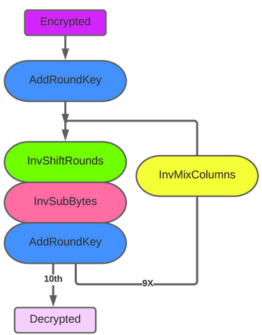
Generally, AES processes data a byte at a time and performs operations on a 16 byte block per iteration. For AES-128, it will run through the flow ten times, with the last iteration not running the "InvMixColumns" State.
|
Add Round Key |
XORs the input with the the 16 byte key. We'll expand on the "round" part of the name later. |
|
InvShiftRounds
|
Scrambles the byte locations around. |
|
InvSubBytes
|
It's a lookup table. Uses the value as the index to a specify 256 byte array called the "Inverse S-Box Table." |
|
InvMixColumns
|
Jumbles everything up! Adds "diffusion" to the encryption. |
That S-Box tho'
We are going to focus on the "Add Round Key" and the "Inverse Substitute Bytes" (InvSubBytes) steps for our attack.
The AddRoundKey just XORs each byte of the buffer with the corresponding byte of the key and places it back into the buffer.
The Inverse Substitute Bytes (InvSubBytes) is just a fancy name for a lookup table comprised of specific constant values. This table is called the Inverse s-Box. So for each of the 16 bytes we perform.
One may ask, "What about the shift rows function in between these two?" Since we are going to be running correlation analysis on all our data, where the bytes exists in the array does not matter to us. Basically we can ignore this step.
Key Schedule
When you dive into AES, the key scheduling step is often skimmed over. For decryption, we need to understand this step.
Before the first byte is ever decrypted, the encryption key gets manipulated. The number of times, it gets manipulated is ten times for 128 bits. You'll see this written as 10 rounds of the key schedule in literature. Luckily, this key schedule is invertible. Meaning, if we determine the key for a particular round, we can easily compute the original key.
For instance, if our key was all zeros. Here is how the key schedule would transpire for each round.

During decryption, the last round of the key schedule is the first round used. So, with a 128bit key, the decryption would use round 10's keys. In the above all zero key example, key_schedule_round_10[0] would be 0xB4.
For the first byte it would look like:
result = inverse_sbox_table[ input_buffer[ 0 ] XOR key_schedule_round_10[ 0 ] ]
Inverse Shift Rows
The only slight curve ball is the order of operations is not byte 0,1, ... 15. Because of the inverse shift rows step, the bytes are not processed in order. However, due to the correlation basis of CPA, which we'll talk about shortly, the order does not matter and the key and it’s location in the key schedule is easily identified. Since it helps during debugging our attack, the byte order will be:
Byte number 0, 13, 10, 7 | 4, 1, 14, 11 | 8, 5, 2, 15 | 12, 9, 6 ,3
The Missing Link in all of this...
For a given byte, on the first round, our flow basically looks like this:
Figure: Exploiting the Inverse Sub Bytes Function

If only we could only see the result here. At this point, the algorithm is completely invertible, meaning if we know the result, we can work backwards and find our Round Key.
This is the basis of this attack!
We can!
Hamming Weight
When a microcontroller loads or stores data, it requires power to change the state of the register's latches. The power consumed to load a 0xDD will be different than that to load a 0x0. A 0xDD 0b11011101 has six 1's and two 0's.
The way microcontrollers store temporary data, means we'll see a different draw for a write of 0xDD and a than that of 0x00. Depending on the design of the microcontroller, we may see a draw or a drop of power usage, but it will be fairly consistent. You'll see this count of one's as the number's Hamming Weight in references. For instance 0xDD would have a Hamming Weight of six.
In the end, we categorize each number [0b00000000 to 0b11111111] by it's Hamming Weight. There should be eight distinct possibilities or relative levels.
To combine these concepts, if we can accurately measure the amount of power the target is using during the load or store, we can get an idea about the data at a given time.
Seems kind of far fetched, but since the inverse s-box is a pseudorandom lookup table, the input is not related to the output electrically at all. The fake "randomness" of these steps, and the sheer amount of captures we take, filters out the noise!
Continue on and it will all make sense.
Attacking the Victim
The attack is broken down into three stages.
- The Reconnaissance Stage
- The Capture Stage
- The Analysis Stage
The Reconnaissance Stage
Microcontroller's Bootloader
A bootloader gets data from an external source for an update. It's here where we'll inject the known data to perform the attack. So yes, we are going to send random data into the victim during an fake update process!
Don't worry, it'll be fine! Trust me...
At first you may be worried about over writing the target. The truth is, all bootloaders have some sort of CRC check after decryption. It becomes mathematically improbably that this check would pass with decrypted random data. Therefore we're going to throw a ton of garbage data to the victim's bootloader and measure it's power usage.
Some bootloaders front load the CRC in cleartext in order to accept the data packet. These style of bootloaders at minimum will always have a flag once the update is complete, so as long as we just program the first block, we will just be stuck in the bootloader each iterative cycle.
None-the-less, you'll need to reverse engineering the Host to Victim update protocol before starting. This process is outside of the scope of this article, but generally consists of an oscilloscope, static dissassembler, logic analyzer, and/or some sort of protocol analyzer. This is your first step and will take some time. You may be lucky, and can hijack the update host using Frida or some other tool. In the end, you'll need to be able to pass data to it via Python.
For my particular target, I found it easiest to create a host micro that converts a serial data stream to our target's i2c protocol. An Arduino or similar will work great for this abstraction layer application and it's highly recommended.
Our Victim's Update Protocol
Our particular target encrypted the header. As seen below, the header contained the CRC, row offset, and the row's data. It always sent 0x90 bytes with a program row size of 0x80 so we knew 0x10 bytes consisted of a header.

You may ask, why did they add 16 bytes when 4 CRC bytes and 2 offset sector bytes would have worked? Remember AES works on 16 bytes at a time, so it most always will be 16 byte aligned.
Setup to Trace the Power
[Review for EEs] Now that we can transfer test data to our target, we need to find a way to gleam side channel information from our target. We've successfully chosen a power side channel attack for this target.
Remember: Power = Voltage * Current
Since, the voltage provided to a microcontroller is regulated, we simplify our power measurement as power is directly proportional to current.
The easiest way to measure the current drawn is to place a small resistor between the VDD source and the target microcontroller. We then measure the voltage drop across the resistor and multiply it by the resistor value to get the current drawn.
Voltage Drop = Current Drawn * Resistance Constant
What's nice about this setup, is we really don't care about the absolute value of current, just how it changes. Therefore, by measuring across this resistor, we are able to log the power drawn over time of the microcontroller. Hooking this up to an oscilloscope we are able to capture this information and relay it to a computer for processing.
You may ask, what about decoupling and bulk caps? We're not looking to run the target reliably over temperature, etc. Given a properly sized resistor, your target will work fine during the duration of the attack. Typical values are anywhere between 10ohm and 200ohm.
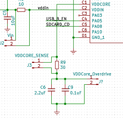
Our Victim
For the Microchip ATSAMD21, the VDDCore is tied straight to the ALU and it's associated buses. For our target, we measure the voltage drop across VDDCORE_SENSE 'R9' to determine the current draw at that instant. Since neither is attached to ground, its easiest to just use a differential probe for this setup. We found 30ohms 1% to work the best in our situation.
The Acquisition Stage
This attack relied on the ChipWhisperer Lite and it's complete ecosystem. The ChipWhisperer is a hardware and software suite for performing Side Channel Attacks. Software-wise, it's a complete programmable ecosystem used to capture power traces and perform all the post processing statistics on the said data. Hardware-wise it's a computer controlled 100mhz oscilloscope and clock generator with some triggering and serial capabilities.
All this said, it's highly recommended to run through all the Chipwhisperer demos before attacking your own hardware (RTFM).
This is how the hardware setup looked.

Using the ChipWhisperer, we duplicated the "Breaking_AES-256_Bootloader" Jupyter Worksheet and began curtailing it to our needs. We then wrote some Python code necessary to communicate with our target's bootloader. Once we had connectivity to the bootloder, we hooked in the differential probe to the ChipWhisperer and started capturing traces.
At this point, take time to really get clean traces and try to align your waveforms. Since I created a host to communicate with the bootloader, I used the host to create a trigger so the ChipWhisperer knows exactly when to start its capture. The closer you can get with alignment now, the easier your life will be in the future.

Tying this all together, we used the ecosystem to automatically create random data, send it to the target, log the power trace with the sent data for future processing.
Once we have the flow correct, and the power traces looking clean, we fired off the system and collect thousands of traces. We now have enough data to run our analysis and extract the victim's keys.
External Oscilloscope and Acquisition Tips
Since we had no access to the target clock we had two choices.
- Recover the Target Clock
- Oversample the power consumption
We chose the latter, as the ATSAMD21 has many internal clock domains running at once and it would be difficult to filter and recover the system clock. Since we gathered the system clock was running at 48Mhz, we determined we needed to use our higher bandwidth lab's oscilloscope for the capture. Luckily it has ethernet and allows us to download the traces for analysis. In a nutshell, this is fairly easy to do using NI-VISA with pyVisa and a bit of Python wrapper code. We then just pull it into our ChipWhisperer Jupyter worksheet. If our TDS 3034B could do it, yours probably can too! My TDS 3034B python code.
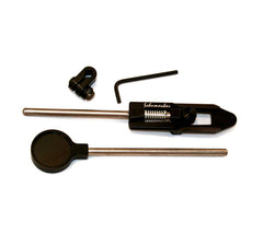
Figure: Differential probe to the oscilloscope for tracing.

Also, if you use an external oscilloscope or Picoscope, you’ll want to set it up to use AC coupling and most likely a bandwidth limit filter. It's much easier to impose a bandwidth filter on the scope than to do so in code!
As I said before, use a differential probe for your front end. Spend time getting the supply side as clean as possible using caps and even ferrite beads. 
The Analysis Stage
To simplify the attack theory (and leaving out the mechanics and why this works):
For each point in our power trace, we ask a question,
"If the byte in key_schedule_round_10[0] was this value, would the power usage at this particular point correlate with this assumption?"
By aligning our traces, and performing this analysis on all our captured traces, for each of the 16 key locations, we find a certain value and time where the correlation is extremely high (a value whose absolute value is approaching 1).

An example of the correlation of x and y for various distributions of (x,y) pairs- Denis Boigelot
Surprisingly quickly, the point in time and value where the key schedule value is being written or read from the microcontroller's bus becomes apparent.
Colin O'Flynn talks about correlation in his Introduction to Side-Channel Power Analysis video at 45:50, however the whole video is highly recommended to watch as it also explains why this works.
Very Important!
Lastly, remember that we have found the round 10 key. You can then use the ChipWhisperer software, or this c code to determine the key for round 0.
Hardware Considerations
Don't Forget about the Loads
I should note, as I got held back with this fundamental for a couple days, we are not necessarily focusing on the exact time the "result" is written into the register. Our attack should have a broad view on every time this byte is being used for the first round of decryption. Remember it is not only written into the register when it is first calculated, but also read from the register when it is used for the following decryption step. It also can become even more prevalent when the cache gets written back or read from. In my particular attack, the power correlation became much more apparent later in the process than when the values were first calculated.
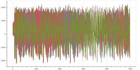
The below power trace is that of the first round of AES128 on our target.
|
Pink: i2c clock from the host used to communicate with bootloader Yellow: Trigger from host Green: Power trace Blue: InvSubBytesAndXOR |

result = inverse_sbox_table[ input_buffer[ 0 ] XOR key_schedule_round_10[ 0 ] ]
The Power Trace (Green) is wrapped by the victim's "InvSubBytesAndXOR" function. The implementers of the victim's bootloader code combined the Inverse Sub Bytes and the the following Add Round Key step which made it a bit more difficult to SCA.
Unknown as to why, the following mix column process still had side channel information about the inverse s-box lookup. We were able to get better signal to noise ratio when we broadened our view. I'm assuming this has something to do with cache, but I honestly do not know.

Above shows the first and second Inverse S-Box Substitution and XOR step. Notice from the purple trace you can see the i2c line acking the data transfer to start the decryption. The blue, wraps around the "InvSubBytesAndXOR" step and is followed by the mix columns step.
Attacking Internal Regulated VddCore
Having an internal VddCore regulator without an external shutdown pin makes the attack a bit more difficult. The easiest method to overcome this is to overdrive the supply on the capacitor side of the resistor, not the end directly connected to the target. For the SAMD21 we found around 1.52v to be sufficient. Start with the VddCore output voltage and slowly increase it by a millivolt until the signal becomes apparent.
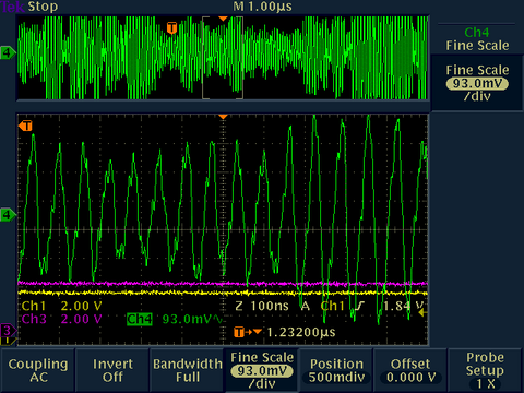
[VddCore internally supplied]
Above you can see the Vddcore regulator switching frequency mixed with the core's current consumption.
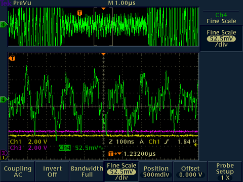
[VddCore externally over-driven]
When we overdrive the VddCore, we now only see the current consumption of the core. Of course, this is not optimal for longevity, but at room temperature, the silicon should hold up for our analysis.
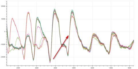
Figure: Bokeh Plot of 50 Traces of the Inverse Sub Bytes and XOR Round Key Step
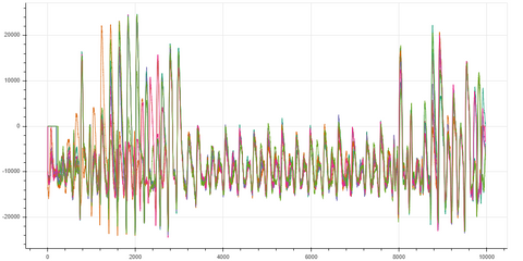
Note you can see the 16 operations of the Inverse Sub Bytes and XOR step. However, notice how little current the operation draws on the ATSAMD21 in comparison to the following mix columns.
Figure: Bokeh Plot of 50 Traces of the Mix Columns Step
Answers to Questions I Had When I Started
- Why not attack round 0 instead of round 10?
You may be wondering why we don't just set our trigger ahead to when round 0 key is being used and do the CPA there? The reason being is we no longer know the input buffer at that point as it has already been manipulated 9 times. -
Why don't we attack the read of the key straight from the register?
Why even attack after the s-box? I touch on it briefly in the The Missing Link in all of this section, but imagine you have a 0x55 and a 0xAA in the round key. Both have the same number of 1's and zeros. We would have a hard time deciphering the true value without a conversion we gain from the Inverse Sbox step. -
How do I know when I get it right?
The correlation, or Partial Guessing Entropy (PGE) indicator on the ChipWhisperer setup really helps you determine these slight variations in the algorithm. This number is your gauge as to if your change helped or hurt your attack. It’s your score card. The PGE does go down as trace data increases. However, it should be obvious which value is the winner. If it is not, then you're doing something wrong.
As seen below, the top row is red as this is one of my test runs with a known key. The big thing is to note the differences between a good and a bad PGE. Although the difference will change with the volume of trace data, we are looking for a PGE that is vastly different than any of the others. If they are not, you're best to adjust your technique before you continue with the actual target. You'll see some 0.410 vs 0.156, this is what we want across the board.
There are many ways to "check your work" once you obtain the key. If you have a couple bytes with a low PGE, you can run the entropy on the output to automate brute forcing the final keys. Remember, most companies are not reinventing the wheel. Check with the vendor bootloader sample to give you some insight into the process. -
What about a non-zero Initialization Vector
I have not been explicit about the mode of AES decryption used in this article, but (CBC) Cipher Block Chaining is pretty standard. Most manufacturers will add an Initialization Vector during this encryption. Luckily for us, this will only make the first 16 bytes invalid and does not affect the rest of the chain. Colin O'Flynn has a method for recovering the IV, but for most people's research, the IV does not matter. In my case the IV was 0's so I did not have to worry about recovering this value.
Figure: Decryption using the Cipher Block Chaining (CBC) mode.-WhiteTimberwolf
-
Can I still do a power analysis based attack if I don't have access to the system clock?
One concept that took me a while to understand is that for power analysis attacks, the target’s clock rate does not necessarily need to be known. Yes, your scope has to have enough bandwidth to capture the power consumption, but even the power filtered down a bit still correlates properly. With that said, the number of traces required is greatly minimized if you synchronize sampling with the target clock.
What You'll Need to Perform Your First Real Attack
Again, I highly suggest working through all the ChipWhisperer DPA tutorials. Be sure to spend time really understanding the examples, not just running through the paces.
Secondly, take your time. The fundamentals really do matter. Here is a list of things you’ll need to do and consider when setting up your attack your target.
- Buy into the fact that at least one of your target devices will never be the same.
- This attack is not going to happen overnight. Take your time, expect a few weeks if not a month.
- Reverse engineer the protocol necessary for the update. We need this to hijack the input buffer. For my attack, I created a simple serial host that took the 16 bytes from the ChipWhisperer software and correctly talked to the victim via i2c. Luckily in our case, the first stage of the victim took a different command than the remaining stages. This is how our victim knew to reset the IV and CBC.
- Optimize the above step. The quicker you can get trace data out, the faster your attack iteration cycle will become.
-
For ultra complex or small victims, you are best off fabricating a separate attack board where you can easily access all power rails and input signals. This allows you to hot air rework the device off of the target and onto your victim attack board when ready. When designing an attack board, be sure to add a possible shunt resistor to all power domains as well as going overboard on filtering caps to the supply side of the shunt resistor. You don’t need to populate them all, but it’s easier than "bodging" ones you missed. As always with test boards, add a metric ton of ground test points. My other suggestion is, even if you are used to using 0402, might as well design using something bigger as you’ll be swapping parts quite a bit.
If your company is paying for it, I would just get the ChipWhisperer level 1 or 2 kit and build a UFO board.
Learn from my mistakes as I did everything I’m telling you not to do.
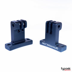
Figure: My attack board. SAMD21 35-WLCSP (2.82mm x 2.53mm)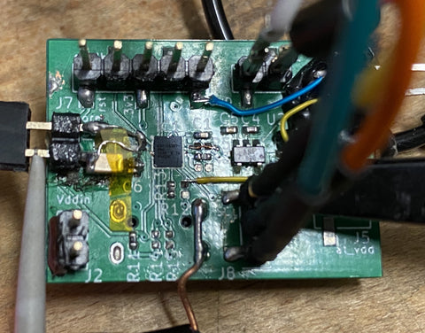
- I suggest running through a simulated attack with a known key on a target you own. Using the simple serial AES sample or an “secure bootloader sample” from the hardware vendor is an easy way to tweak your setup to best extract keys.
TIP: Refine your filtering caps, number of traces, bandwidth, mv/div and even your trigger before attacking the real victim. Once you have these figured out, the real attack will happen quickly. -
It's extremely important that the traces need to be aligned for a proper CPA attack. Get to know the Sum of Absolute Difference (SAD) Pre-Processing built into the ChipWhisperer library. For my particular attack. I used a coarse SAD filter first to get the signals fairly aligned as we were not synchronized with the target. Then I used a secondary extremely fine SAD to align the signals on an abrupt current swing like seen below.
The particular algorithm I attacked did not have a time deterministic mix columns function. Therefore, I found it easiest to align and attack four bytes at a time as they got processed by the mix columns function. To write this another way: I first attacked key bytes 0, 13, 10, 7 then realigned to the next mix word
4, 1, 14, 11 then realigned to the next mix word
8, 5, 2, 15 then realigned to the next mix word
12, 9, 6 ,3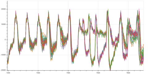
It is possible this non-deterministic aspect of the algorithm can be compromised by another side channel attack! - Jupyter is a really nice way of logging your changes and attack results. Be sure to embrace its power during your quest.
- Finally, you really just need to do an SCA attack. Reading about it and trying to wrap your brain around the complexities does not work. You need to work through a victim yourself to grasp these complex concepts.


Conclusion
Like many, I owe a ton of gratitude to Colin O'Flynn and his NewAe team. It amazes me how powerful their ChipWhisperer tool set is for the price and the constant refinements they make to the already awesome product. I'm not affiliated with them, I'm just an extremely impressed customer.
I have just scratched the surface of SCA and looking forward to continuing my research. If you have noticed anything conceptually wrong in this article feel free to drop me a line on twitter at @gethypoxic. I'm not one to answer direct DMs for support, but suggest reading NewAE's forums instead.
Bio
Mark Kirschenbaum owns and operates Hypoxic, an action sports electronics company. Primarily developing camera controllers, Mark has continuously reverse engineered products to add hardware and software functionality for his clients. Prior to Hypoxic, Mark developed programmers and debuggers for a leading embedded microcontroller company. Side Channel Attacks have become Mark’s area of interest and he looks forward to sharing his real world experiences with other like minded hackers.
Twitter @GetHypoxic